Technical Information - Speeds & Feeds
CALCULATION OF SPINDLE SPEED FOR BALL NOSE TOOLS
- Choose the cutter diameter and depth of cut (DOC) you want to run.
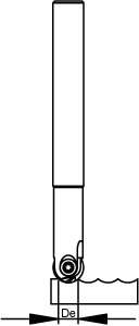
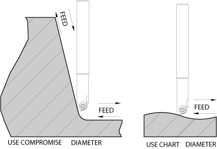
- From the chart above find the “effective cutter diameter’,(De). If your workpiece is relatively flat, use the diameter directly from the chart.
- If your workpiece has steep walls, the effective cutter diameter must be further calculated. This “compromise diameter” can be found by averaging the “chart”
Example: 0.500” insert; 0.020” DOC; workpiece with steep walls De from chart = 0.196“ compromise dia. = (0.196 + 0.500) / 2 = 0.348” - Pick a cutting speed (SFM) from the "Speed Chart" based upon your workpiece material type and
hardness. Note: pick a speed slightly above the middle of the corresponding range.
Example: Alloy Steels and Tool & Die Steels: 350HBN 300-750 SFM ... Pick: 550 SFM - Calculate RPM. RPM = (SFM x 3.82) / Effective Cutter Dia.
Example: RPM = (550 x 3.82)/ 0.348 = 6037 ... To achieve an average of 550 SFM while milling at a depth of 0.020" with a 1/2" diameter tool cutting a steep walled work piece of P20 at 35 HRc (350 HBN).
FEED RATE CALCULATION
Once you have calculated your spindle RPM, you can now calculate the appropriate feed rate.
- Select an appropriate chip thickness for the material type and hardness you are cutting. Note that one should start at the smaller end of the scale for safety reasons. Cutters smaller than 1/2” (12mm) should decrease the chart numbers by as much as 50%.
Example: Using the same criteria as the spindle speed calculation, RPM = 6037; from the chart, chip thickness is 0.005", and all of our ball nose finishers have 2 flutes. i.e.- 6037 x 0.005 x 2 = 60.37 IPM - Your FEEDRATE (inches per minute) can be calculated by the formula: RPM x chip thickness x # of flutes.
Calculate De = Effective Cutting Diameter
 DE
DE| Insert Diameter | ||||||||
|---|---|---|---|---|---|---|---|---|
| DOC | 0.250 | 0.312 | 0.375 | 0.500 | 0.625 | 0.750 | 1.00 | 1.250 |
| 0.005 | 0.070 | 0.078 | 0.086 | 0.099 | 0.111 | 0.122 | 0.141 | 0.158 |
| 0.010 | 0.098 | 0.110 | 0.121 | 0.140 | 0.157 | 0.172 | 0.199 | 0.223 |
| 0.020 | 0.136 | 0.153 | 0.169 | 0.196 | 0.220 | 0.242 | 0.280 | 0.314 |
| 0.050 | 0.200 | 0.229 | 0.255 | 0.300 | 0.339 | 0.374 | 0.436 | 0.490 |
| 0.075 | 0.229 | 0.267 | 0.300 | 0.357 | 0.406 | 0.450 | 0.527 | 0.594 |
| 0.100 | 0.245 | 0.291 | 0.332 | 0.400 | 0.458 | 0.510 | 0.600 | 0.678 |
| 0.125 | 0.250 | 0.306 | 0.354 | 0.433 | 0.500 | 0.559 | 0.661 | 0.750 |
| 0.156 | 0.312 | 0.370 | 0.463 | 0.541 | 0.609 | 0.726 | 0.826 | |
| 0.188 | 0.375 | 0.484 | 0.573 | 0.650 | 0.781 | 0.894 | ||
| 0.250 | 0.500 | 0.612 | 0.707 | 0.866 | 1.00 | |||
| 0.312 | 0.625 | 0.739 | 0.927 | 1.082 | ||||
| 0.375 | 0.750 | 0.968 | 1.146 | |||||
| 0.500 | 1.000 | 1.225 | ||||||
| 0.625 | 1.250 | |||||||
Steep & Flat Workpieces

Speed Chart (SFM)
| Material | Hardness (HBN) | Cutting Speed (SFM) | Chip Thickness Ranges* | |
|---|---|---|---|---|
| Uncoated | Coated | |||
| Plain Carbon Steels | 50-180 | 70-700 | 400-950 | (0.004-0.012) |
| 180-330 | 200-500 | 350-800 | (0.004-0.012) | |
| Alloy Steels and Tool | 130-330 | 200-450 | 350-800 | (0.003-0.011) |
| & Die Steels | 330-450 | 300-700 | (0.003-0.011) | |
| Stainless Steels | ||||
| 200 & 300 Series | 130-330 | 200-400 | 250-600 | (0.004-0.012) |
| 400 & 500 Series | 130-330 | 200-450 | 250-575 | (0.003-0.011) |
| 330-420 | 150-300 | 200-450 | (0.003-0.011) | |
| PH Series | 140-380 | 180-250 | 250-550 | (0.003-0.010) |
| Grey Cast Irons | 110-320 | 300-500 | 350-650 | (0.003-0.014) |
| Ductile & Maliable Cast Iron | 120-330 | 250-450 | 300-620 | (0.003-0.011) |
| Nickel Base Alloys | 140-380 | 50-250 | (0.002-0.009) | |
| Titanium Alloys | 110-300 | 100-240 | 135-380 | (0.003-0.010) |
| 300-400 | 80-200 | 100-280 | (0.003-0.010) | |
| Aluminum-Low Silicone | 750-1800 | 800-3500 | (0.003-0.018) | |
| Aluminum-High Silicone | 250-800 | 300-1000 | (0.003-0.018) | |
| Graphite | 450-1000 | 800-1500 | (0.003-0.016) | |
*Chip Thickness Chart
- Use this chart for cutters of 1/2" Ø (12mm) and larger
- For cutters smaller than 1/2" decrease chip thickness up to 50%
DOC is less than 50% of insert diameter.
Chip Thinning Multiplier
Compensate the feed rate for the chip thinning that occurs. This is a function of the ratio between the insert diameter and the depth of cut. DO NOT USE the feed rate compensation or the effective cutting diameter chart when side wall milling. Your feed rate compensation can be calculated by: (D(insert Ø) / De(from chart)) x IPM from above calculation. 0.005", which helps promote tool life.
